Attenzione! La nuova versione dello shield viene fornita già montata.
Tratto da: http://www.ladyada.net/make/logshield/solder.html
 |
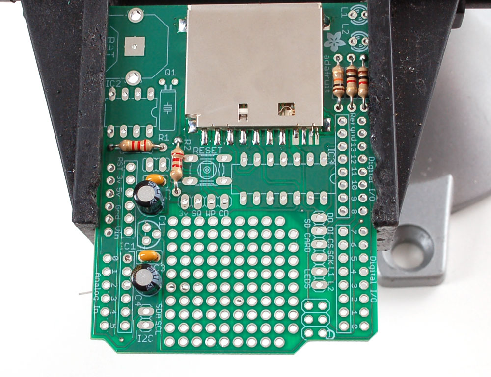
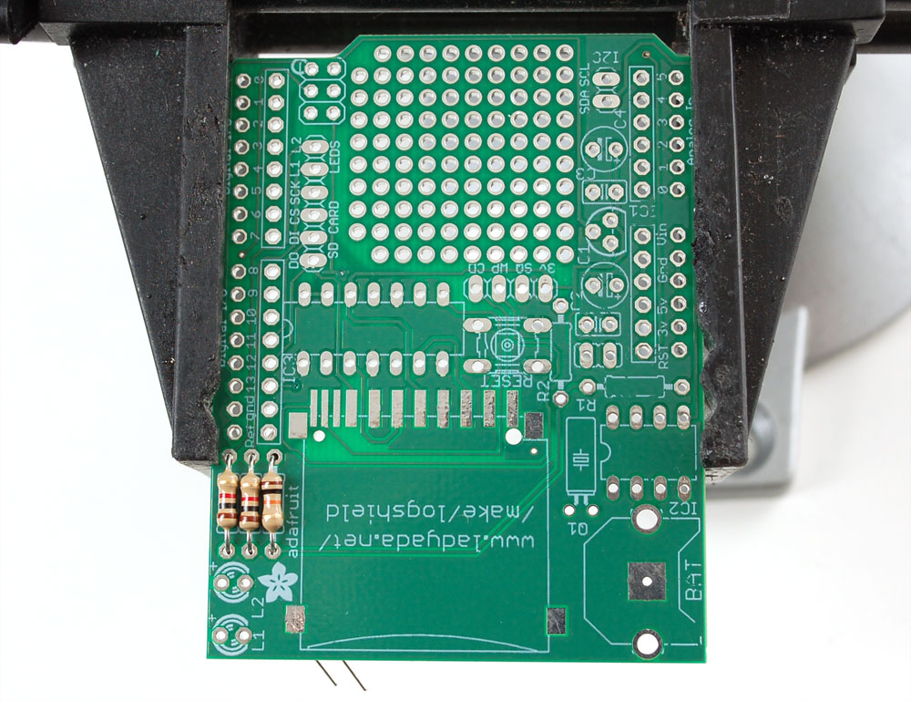
Prepare to assemble the kit by checking the parts list and verifying you have everything! Next, heat up your soldering iron and clear off your desk. Posizionare la scheda in una morsa in modo che si può facilmente lavorare su di essa |
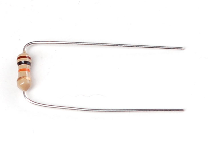 |
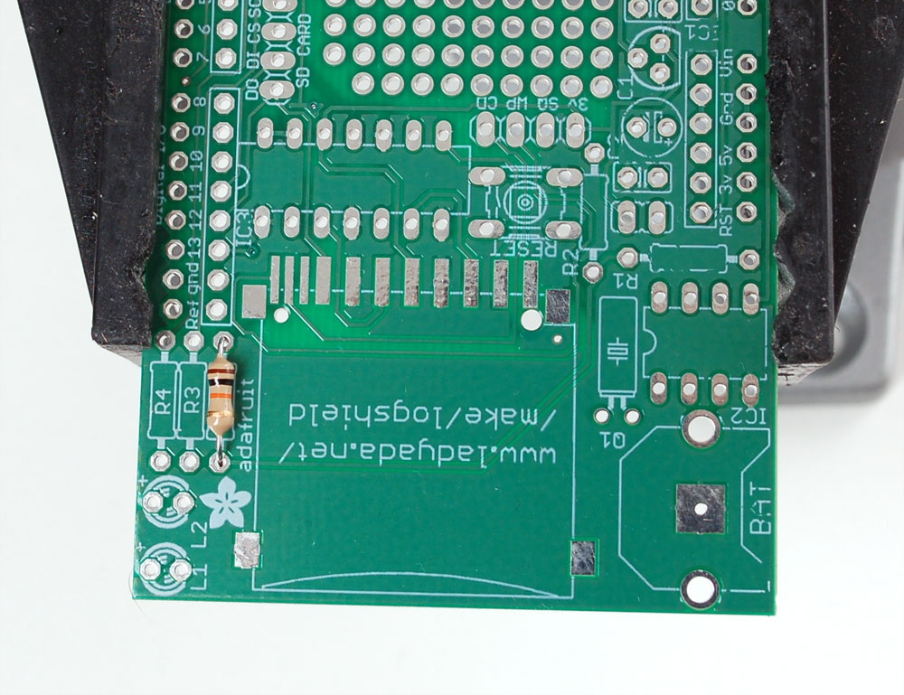
La prima parte che andremo a saldare è una resistenza da 10K. La resistenza di 10K è a strisce Marrone Nero Arancione Oro. Piegare la resistenza in un punto fermo, come mostrato. |
|
|
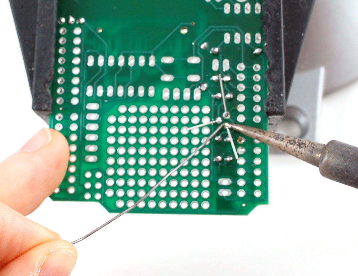
Posizionare la resistenza nella posizione contrassegnata R5 . Le resistenze non hanno polarità che significa che si può mettere in 'in entrambe le direzioni' e funziona bene. Piegare le gambe a filo in modo che la resistenza si trovi piatta contro il circuito stampato.
Questa resistenza è necessaria per mantenere la scheda SD disattivata quando non in uso -Questo impedisce scritture accidentali alla scheda che potrebbero danneggiarla!
|
|
|
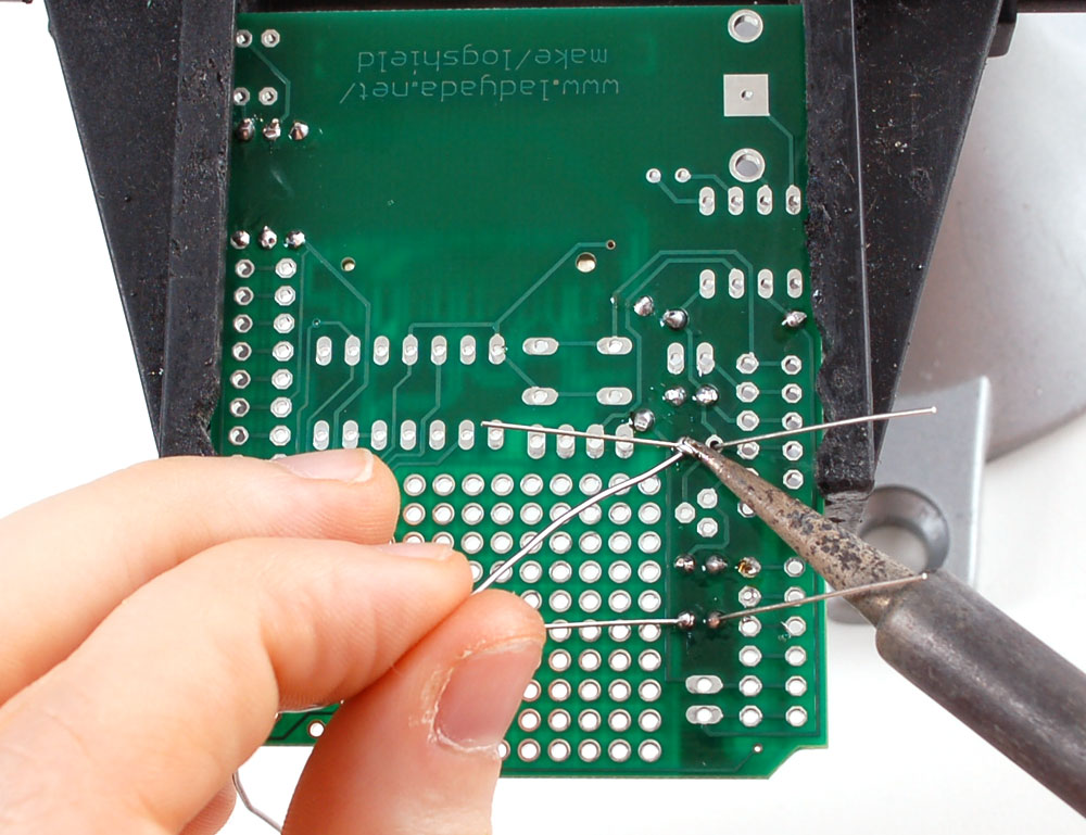
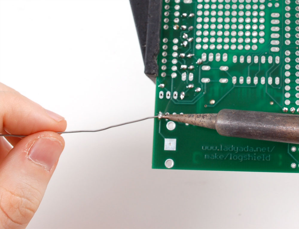
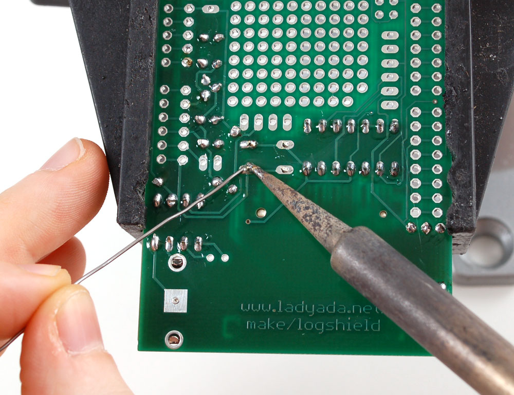
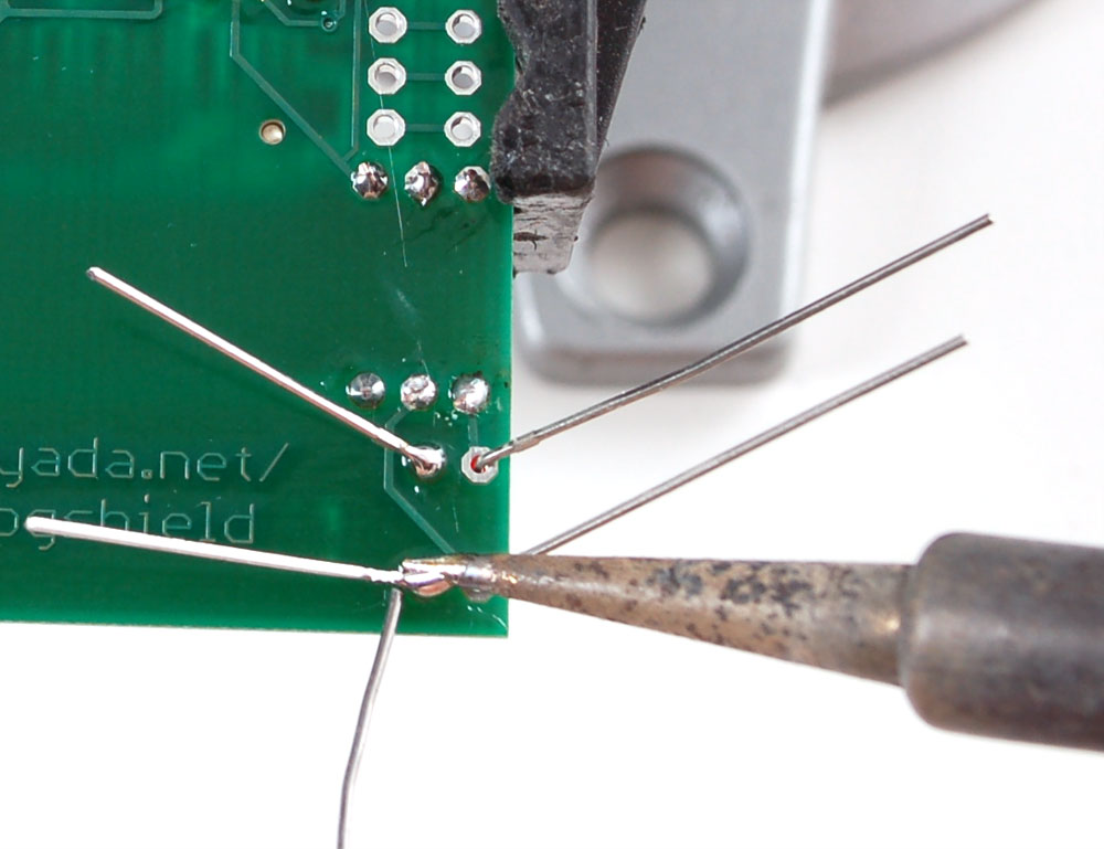
Girare il PCB sopra. Usa il tuo saldature , salda sia il pad (l'anello d'argento attorno al foro) e piombo (filo), al tempo stesso per 2 o 3 secondi. Poi colpire l'estremità del cavo per creare una nuona saldatura. Fate questo per entrambi i cavi. |
|
|
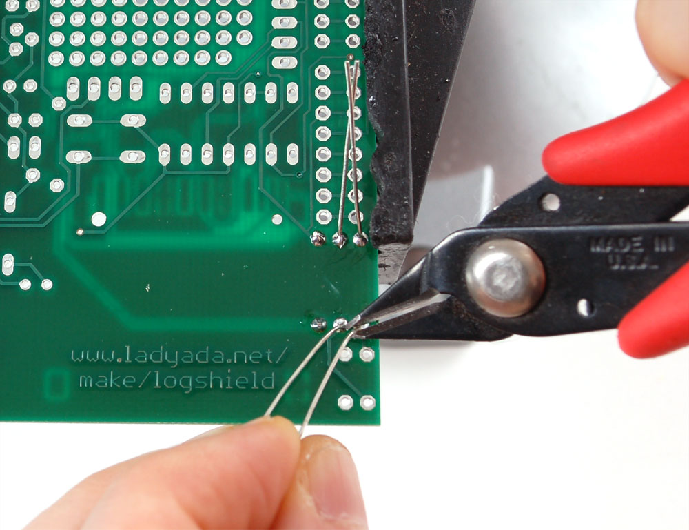
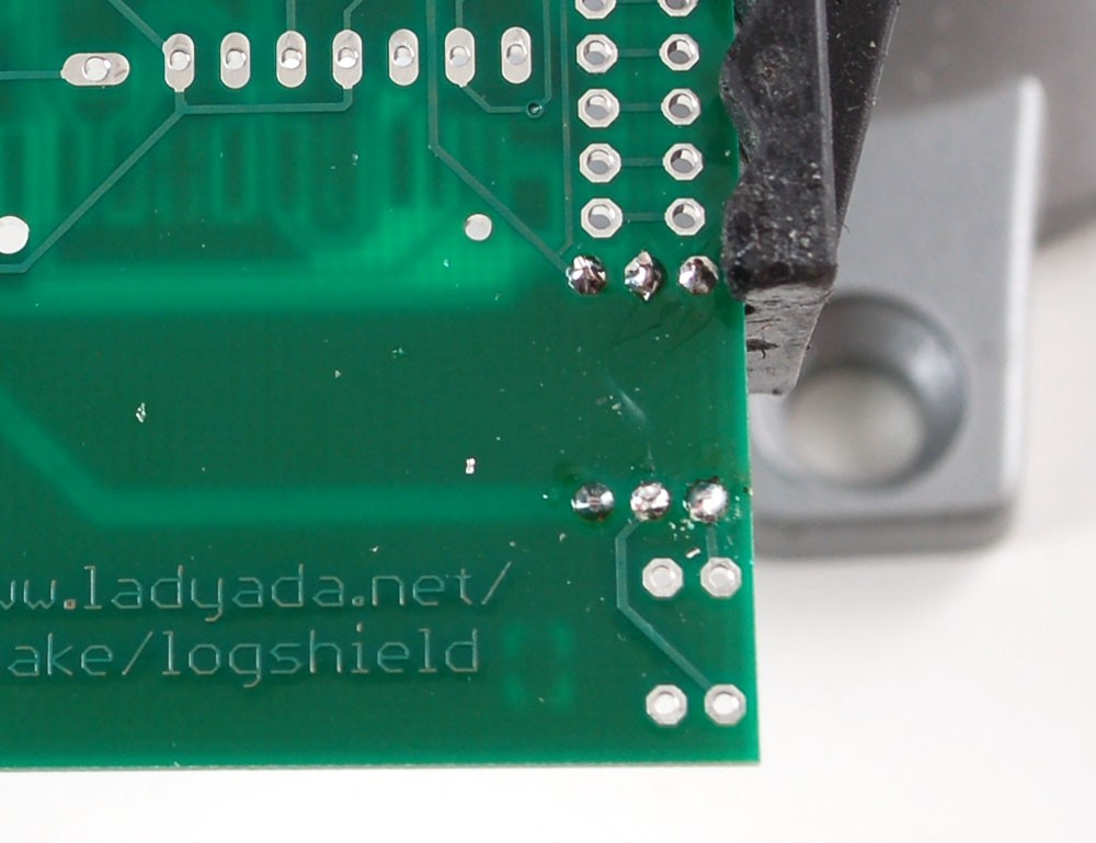
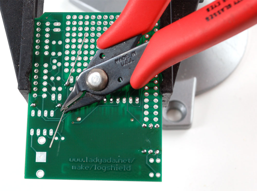
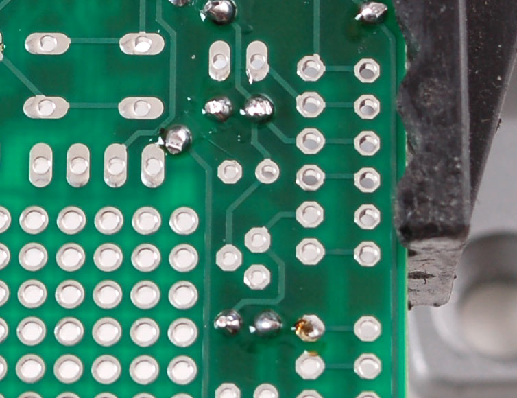
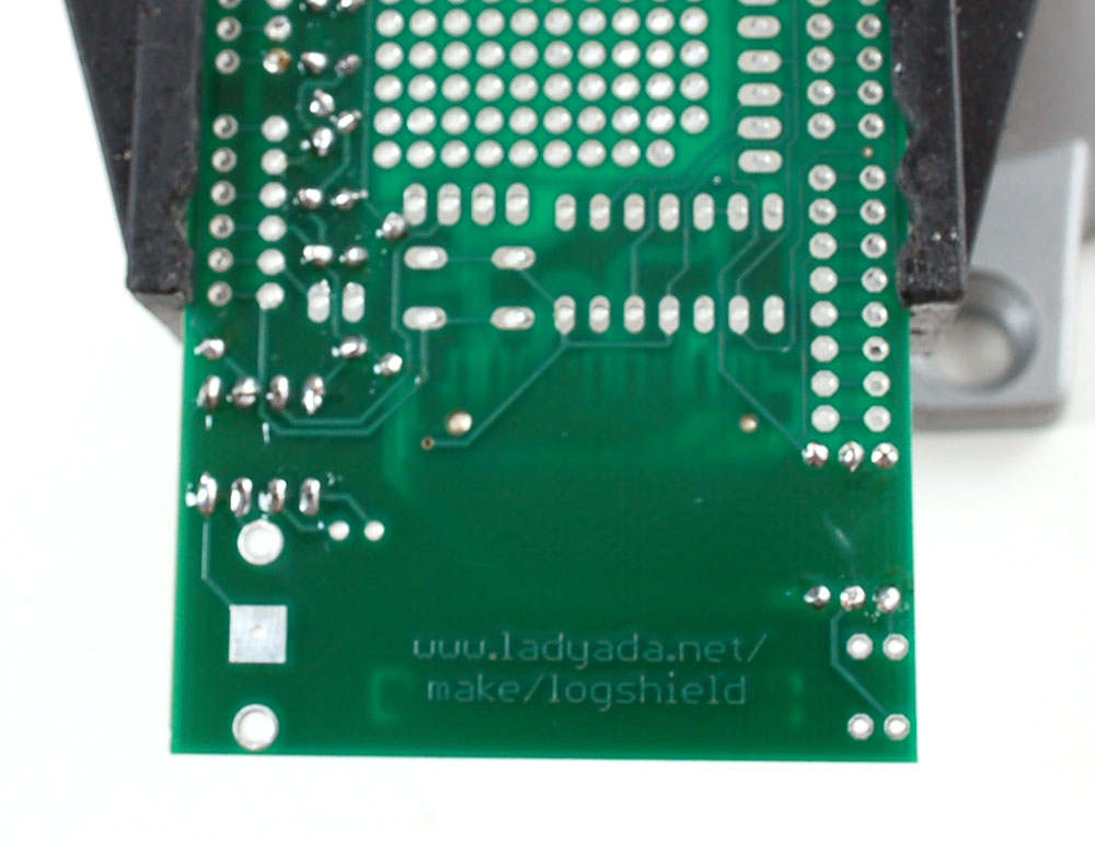
Usando il tronchesino, tagliare i cavi lunghi appena sopra il giunto di saldatura. |
 |
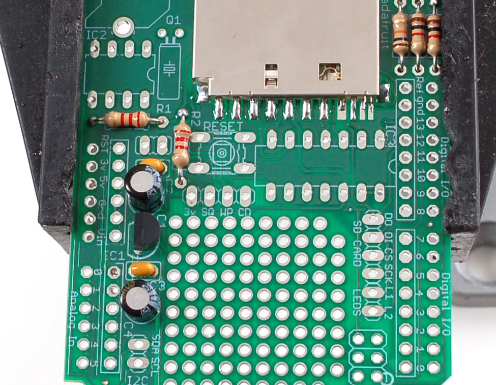
Le prossime due resistenze sono 1.0K - le strisce di colore sono Marrone Nero Oro Rosso.
Piegare e metterle negli slot R3 e R4
Questi resistori impostano la luminosità dell'indicatore due LED rosso / verde |
|
|
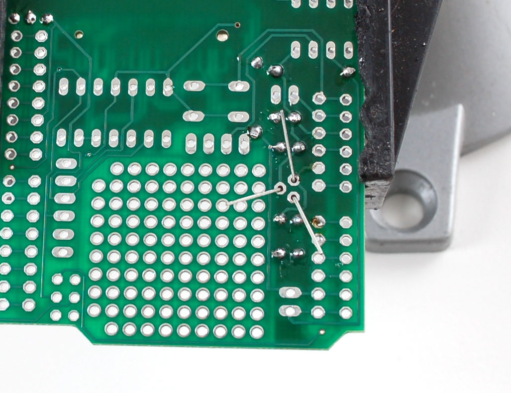
Capovolgere il PCB e saldare le 2 resistenze. |
|
|
Taglia i fili delle resistenze |
 |
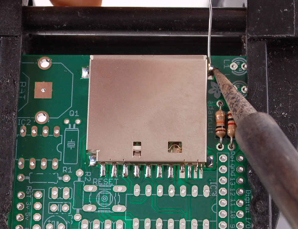
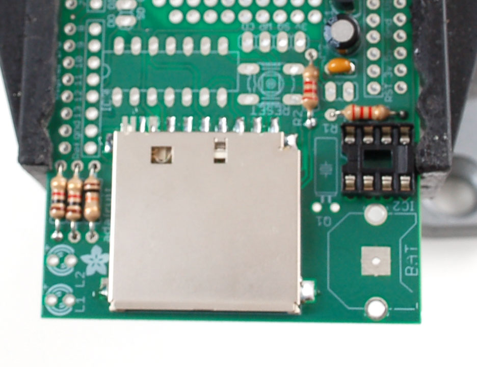
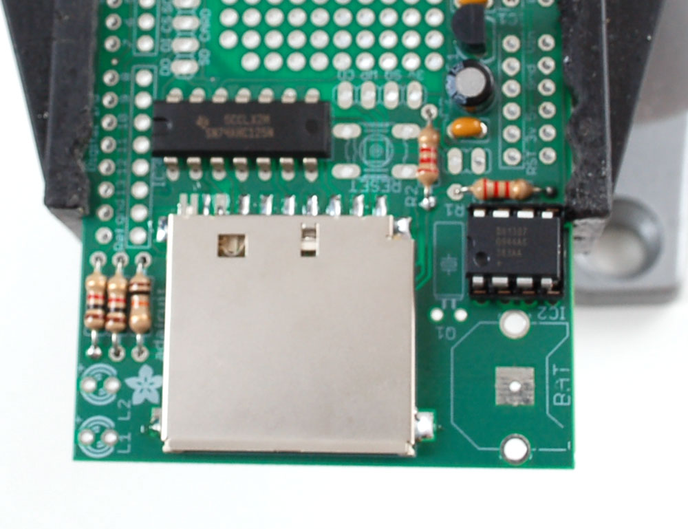
Una volta che sono state saldate le resistenze, è possibile di fare il contenitore della carta SD. Il contenitore è a montaggio superficiale (non ci sono fili che passano attraverso la scheda), ma la distanza è molto generosa, per cui non sarà difficile.
Il supporto è dotato di due dossi che 'scattano' quando posizionati sul PCB. Assicurarsi che i dossi siano inseriti e il supporto sia in posizione piana. |
|
|
The first step to soldering the holder is to 'tack' it in place. On the sides are 4 large tabs. Heat both the pad and tab together for 3 seconds and solder the tab down. Repeat for all 4 tabs. When you're done you shouldn't be able to move the holder. |
|
|
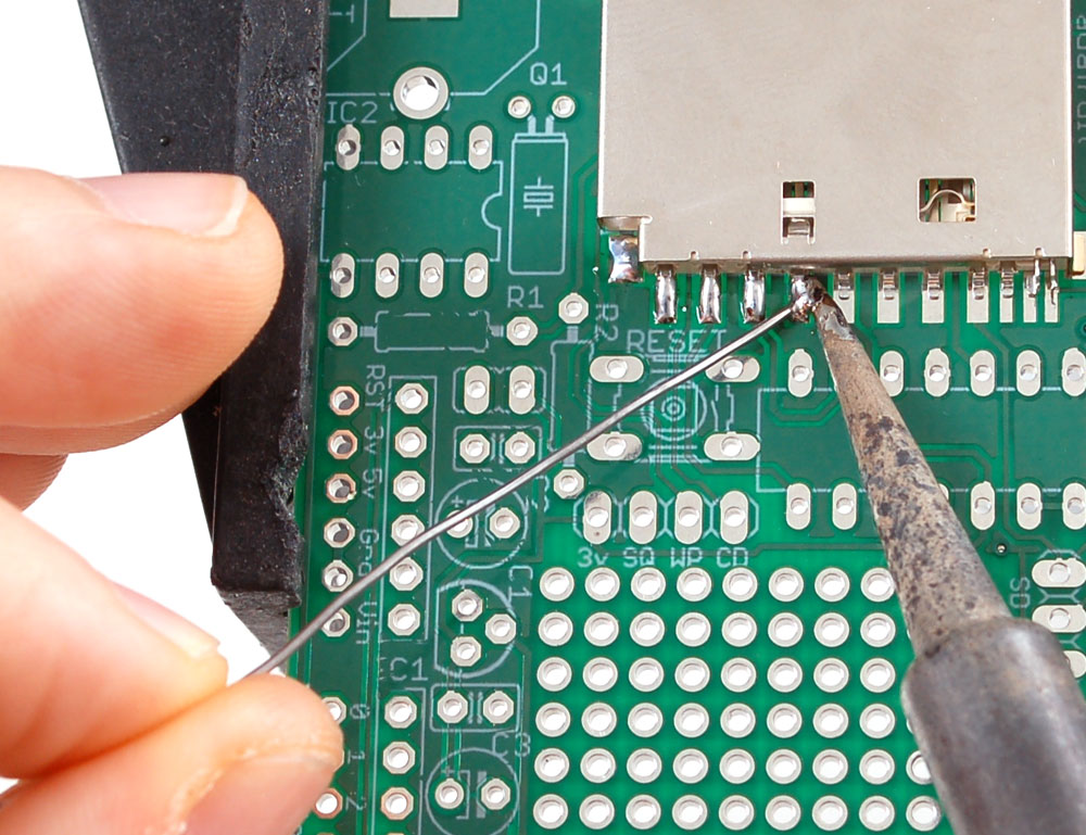
Next, solder the 8 large leftmost pins of the holder to the corresponding pads. (in the photos, the 8the one doesnt look completely soldered but it is) Use a sparing amount of solder so that you wont end up bridging two pins by accident. If you aren't skilled at SMT soldering, you can simply skip the last three smaller pins, they're not at all necessary |
|
|
We will now solder in the two 2.2K resistors (Red Red Red Gold) into the two slots labeled R1 and R2 These two resistors are used by the RTC chip data lines. |
|
|
Solder the resistors using your now-expert resistor soldering skills |
|
|
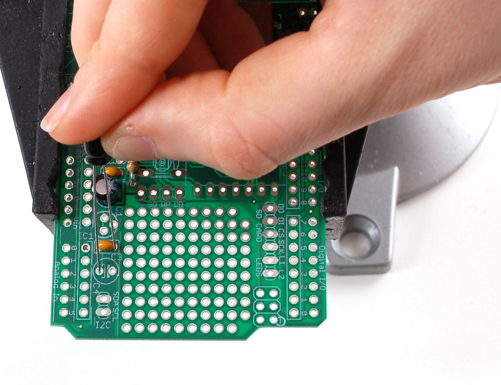
Next we will install the two yellow ceramic capacitors C2 and C3. Ceramic capacitors are not polar so they can be inserted either way and will work fine. Bend out the leads like the resistors to keep them flat against the PCB |
|
|
Place, solder and clip the capacitors. |
|
|
Next are the electrolytic capacitors C1 and C4. Electrolytic capacitors are polarized and must be placed correctly. The longer lead of the capacitor is the positive (+) lead. Make sure this lead is placed in the hole marked with a +. Look carefully before soldering to make sure you got this part right!
|
|
|
Solder and clip |
|
|
Next we will solder in the 3.3v regulator. The regulator is in a TO-92 package, with a semi-cylindrical plastic part and three legs. Insert it into the location marked IC1. Because of the way the pads are layed out, the regulator wont sit flat against the PCB. Thats OK, it should stick up a little bit. Make sure the flat side of the package matches the outline on the silkscreen Solder and clip the three leads |
|
|
Next we will place and solder the 8 pin socket. The socket is for protecting the clock chip and making it easy to insert and remove. Unfortunately, RTCs often shouldnt be removed which means that placing this part is not always preferrable. If the loggershield is going to be used in a place where the chip may get knocked out, you may want to skip the socket and just solder the chip in The socket has a little notch in one end. That notch should match the one in the picture silkscreened onto the circuit board. This will help you place the chipin properly later. In this photo its on the LEFT You may need to solder one pin of the socket while holding it it in with a finger (or tape) as the legs aren't long enough to be bent while in place. |
|
|
Now you can place IC2 the DS1307 RTC chip into the socket by gently bending the pins in so that they line up with the socket and the dot and notch in the chip are on the same side as the socket notch. The RTC is what keeps time when the power is out, its a very very very low power microcontroller and crystal that will keep time for years on a tiny coin cell. This way you can mod your clock with ease and not have to reset it after power loss. The next chip IC3 is the 74AHC125 which is the 3.3V buffer chip that converts the 5V signals from the Arduino to the 3.3V SD-card IC's must be placed a certain way, or they dont work. Make sure you get this right because if the part is in wrong its a real pain to fix! On one end of the chip is a round notch. Make sure this notch matches the silkscreen underneath where there a similar round notch. In thie photo its on the LEFT Solder in all the pins of the chip |
|
|
First, melt a tiny bit of solder onto the center tab of the battery holder BAT. This will make good contact with the battery.
|
|
|
Now place the 12mm coin battery holder BAT and the 6mm button RESET. The button is a symmetric part so it can go in two ways. Line up the metal legs with the holes in the circuit board and snap it in. The button should sit flat against the circuit board. Tack solder one side of the battery holder so it doesnt fall out when you flip over. |
|
|
Now solder the button and battery holder into place. There's nothing to clip. |
|
|
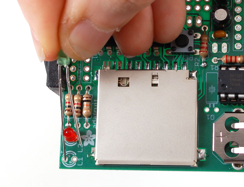
Next are the red and green indicator LEDs. LED stands for Light Emitting Diode, and they must be placed correctly or they wont work. To make sure the LEDs are installed properly, check that there is a lead that is longer than the other. This lead is the positive (+) lead. Make sure that this lead goes into the hole marked with a + on the PCB silkscreen, as shown. |
 |
Next is the 32.768 KHz watch crystal Q1. The crystal is the same as whats in your 'quartz' watch or clocks - it is the thing that ticks to tell time. The crystal is nonpolar. |
|
|
Solder and clip the two LEDs and crystal |
|
|
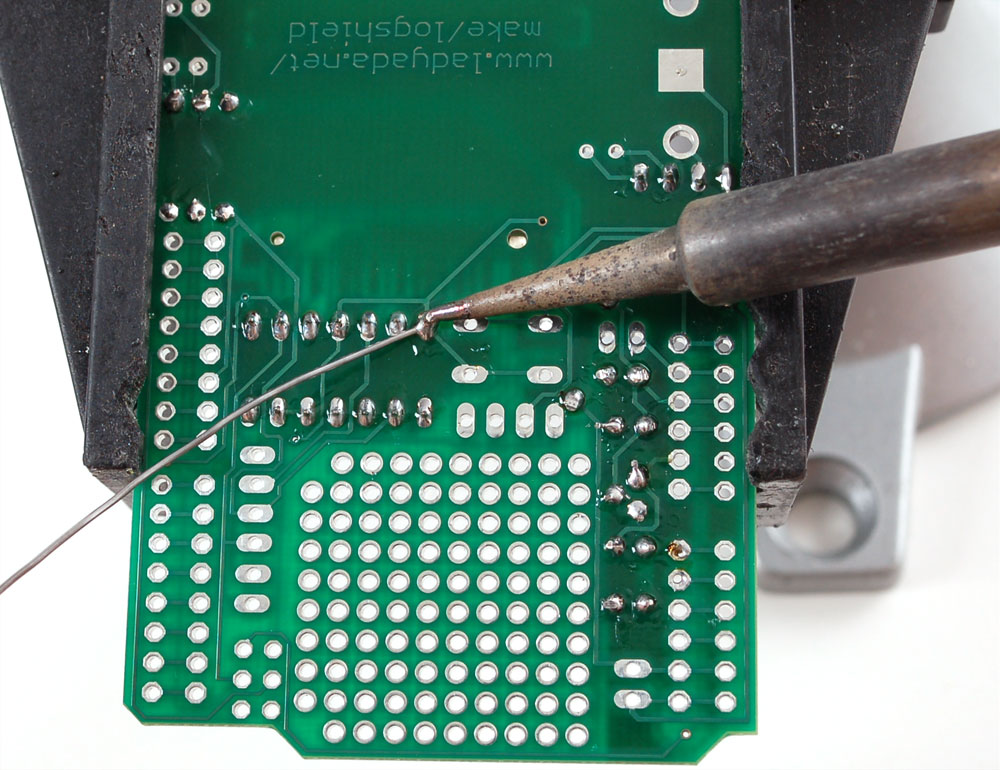
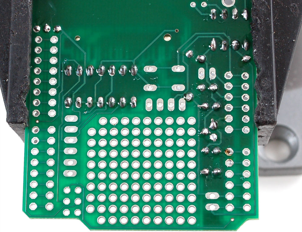
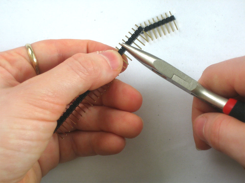
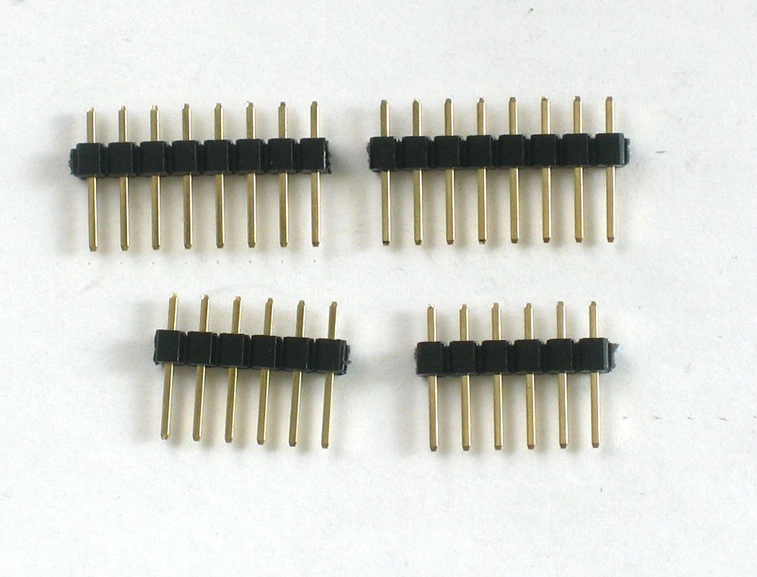
Next, break the 36-pin header strip into smaller sections so that the shield can be placed on the Arduino. You can use pliers or diagonal cutters. You will be able to perfectly snap the long strip into 2 8-pin strips, and 2 6-pin strips. |
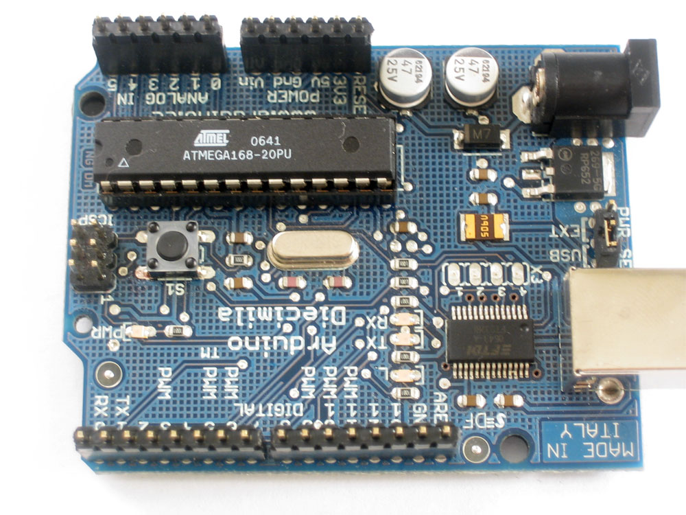 |
Put the long ends of the male header in to the female header on the Arduino, as shown |
|
|
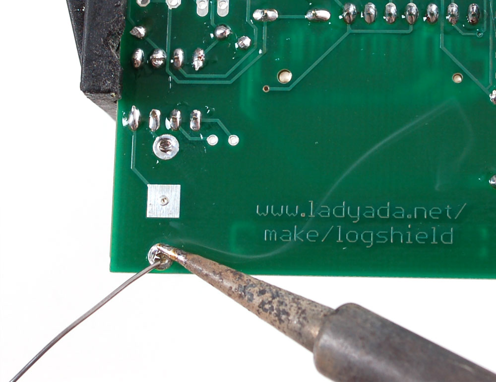
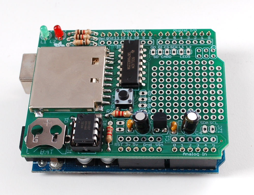
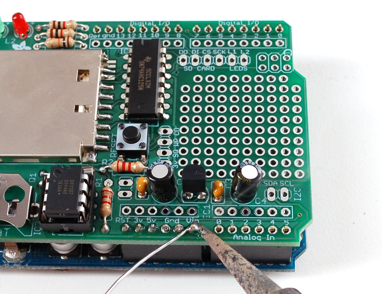
Put the shield on top of the Arduino, so that the male header aligns with the solder holes. Solder every pin of the male header. Keep the shield on the Arduino to make the job easy. Once you're done, you can remove the shield from the Arduino. |
 |
The last assembly step is to insert the battery. The flat side goes up. It will last years so you will only have to do this once. |
 |
You're done! Now you can get an SD card and start reading the usage documentation! |